Emerging Need for Over-the-Air Test Methods
The deployment of mmWave technology is synonymous with 5G rollout and the initial results for faster links are amazing. For example, using a mmWave band, the prospects of a 1-2 Gbps link means a typical HD movie can download in less than a minute. An upload link of 30 Mbps also enables the transfer of videos back to the cloud at a record pace. These user experiences are enabled by the antenna links between smartphones and small cells, and are worth closer inspection.
In a previous blog post, The Great Migration to 5G is Underway, we discussed the signal distribution infrastructure, including the 5G-IF mechanism. In this companion post, we’ll discuss the engineering marvel in the mmWave beamforming module that represents the smartphone’s antenna, including the workflow from design to production.
Design for the Link Budget
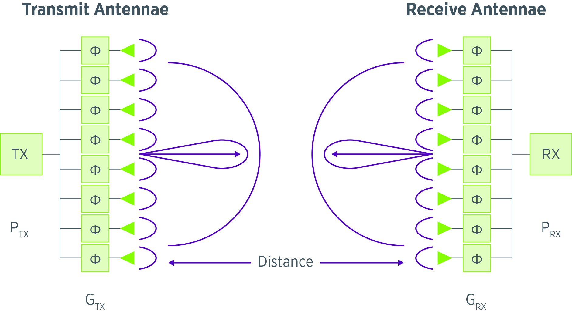
In the design phase, all wireless links must undergo rigorous calculations to ensure adherence to a link budget. These calculations are built on wireless parameters, as simplified in the following illustration, to ensure optimal performance. In this case, we focus on the mmWave application as evident by the antenna array (instead of a single antenna element).

On the transmit side of the link, the transmit power (PTX) and transmit antenna gain (GTX) set initial conditions for coverage. On the receive side, the receive power (PRX) and receive antenna gain (GRX) complete the link. The separation in distance (D) between transmit and receive determines constraints to the coverage. The Friis equation is what governs these link budgeting calculations, which was derived by Herald T. Friis at Bell Labs in 1945.
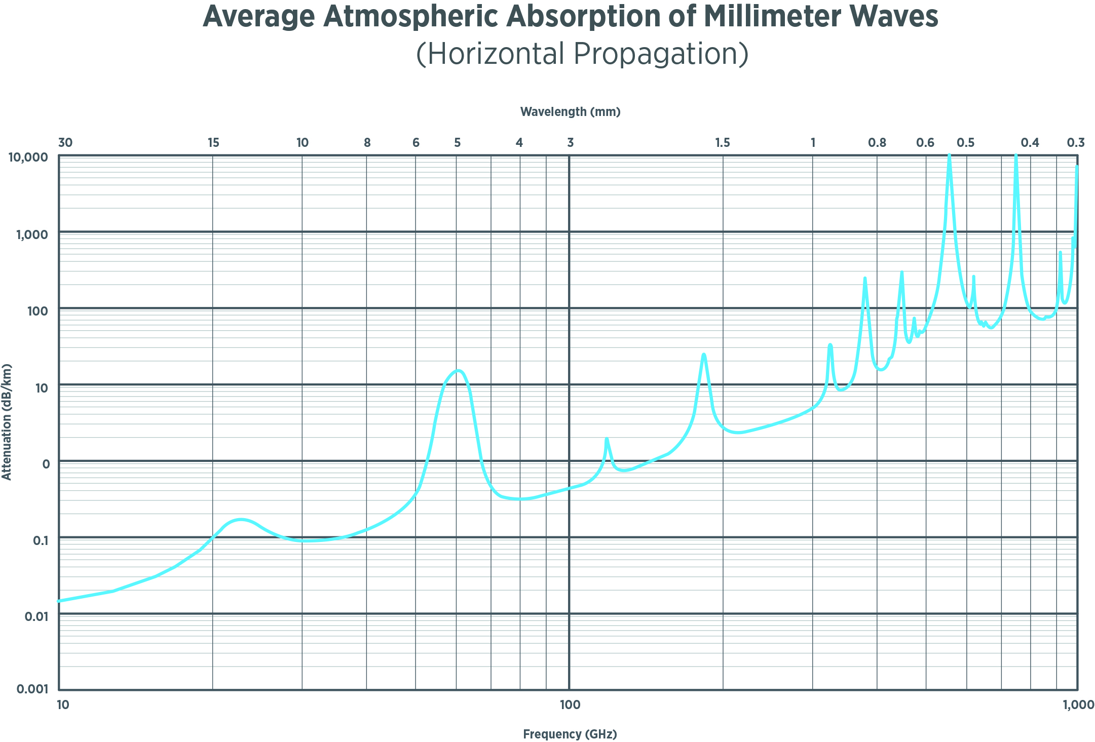
Lastly, the link budget must also consider the following atmospheric absorption characteristics, especially the higher attenuation that occurs with higher frequency, and can vary with elevation and levels of humidity.

The engineering marvel in mmWave links is related to the antenna gain in the Friis equation. With smaller wavelengths (e.g., 60 GHz is 5 mm), it is possible to build an electrically large antenna array to increase gain; in fact, it is this beamforming technology that truly enables mmWave links for 5G.
Antenna in Package (AiP)
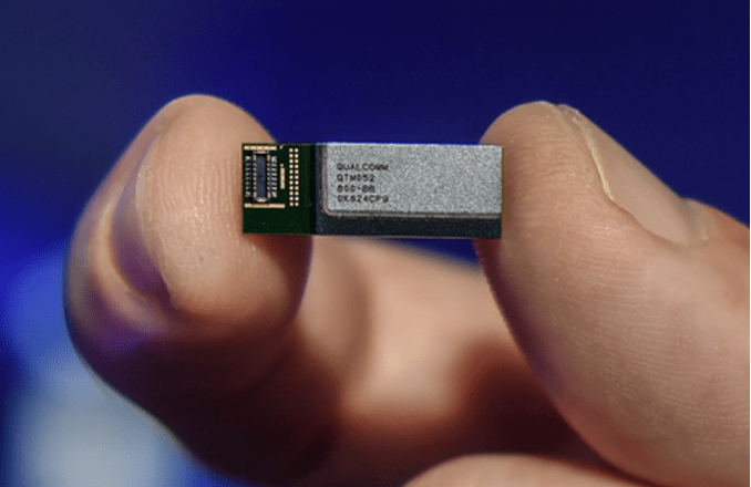
As any teardown of a 5G smartphone will reveal, there are multiple antenna modules distributed throughout that comply with the predetermined mmWave link budget. These antenna modules look like the following antenna in package (AiP) from Qualcomm, which becomes the device under test (DUT) for high volume manufacturing consideration.

Note the thin package profile that fits within the compact 5G smartphone design. Multiple instances of this antenna module are distributed around the perimeter of the 5G smartphone as part of the mmWave technology deployment. Similarly, a corresponding antenna in the small cell base station is necessary to establish a connection. In this way, the mmWave link is ready to transfer data.
Trailblazing New Over-the-Air Test Methods
The question to explore is how to test this emerging mmWave device where embedded mmWave circuitry and beamforming antenna structure for transmit & receiver operations exist. With the antenna as part of the package, testing must evolve to include over-the-air (OTA) methods that are convenient in high volume manufacturing environments.
As a quick antenna primer, during the design phase, an anechoic chamber is necessary to characterize this wireless device. In this far-field approach that emulates how it will deploy, the device is placed on a pedestal and rotated to reveal the antenna pattern versus the DUT’s physical orientation. The chamber serves two purposes: first, prevents interference from nearby signals and second, creates a reflection-free environment for test. The overall size of the chamber is proportional to the operational wavelengths and, in the case of mmWave technology, the chamber is relatively small. However, not small enough for the kind of automation necessary in production.
The adaptation required to create an OTA insertion is shown in the following new silicon workflow. After wafer sort, the beamforming module requires test to reveal packaging defects (and outliers). An OTA insertion with a higher site density will lower cost of test and accelerate the mmWave technology adoption (compared to lower site density).

The workflow for RFIC test during wafer sort is straightforward in that it must produce known good dies (KGD) for subsequent packaging activities with the antenna structure. So, the challenge is in how to create an OTA solution that scales for manufacturing.
The Chamber Matters in the OTA Design
First, as part of our test strategy, we consider a single site design approach. Afterwards, the single site design shall easily extrapolate to the desired site density to meet cost of test targets. This design approach begins with the selection of a standard handler for understanding available application space, antenna placements, part handling, and future-proof for site density. Leveraging a standard handler controls costs by leveraging existing RF handlers for economy of scale benefits.
The initial issue, compared to the anechoic chamber approach, is that this conventional chamber size, even a compact range, is impractical for interacting with a standard handler. Instead, a smaller chamber is necessary that optimizes for mmWave best practices and creates a scalable path to higher site density. Each anechoic chamber will similarly encapsulate the DUT and require additional design optimization depending on the target wavelength and the package size.
Next, we consider the chamber design process as part of the overall test strategy. The starting point is usually a proven engineering evaluation kit; otherwise, a new design from scratch is necessary. Either way, the chamber design usually requires an antenna guru to design for far-field by building models so predicted versus actual result comparisons are possible between the larger anechoic chamber and the smaller production-friendly variant. As a reminder, we need this single site to produce repeatable results where every dB matters in these licensed mmWave bands. The complexity in the chamber design is nontrivial and must also accommodate the antenna package form factor, size and beamforming antenna layout, as well as the variations that will occur as the mmWave module undergoes optimization for deployment.
Along with the chamber design, we need to satisfy physical layer interconnect prerequisites, including signal distribution. The single site design will optimize for the bore sight of the beamforming antenna, including both horizontal and vertical polarization in electromagnetic (EM) signals, which is not too difficult of a problem to solve.
Related to interconnects and chamber design, we need to develop our test strategy for the antenna beamforming function, which is most affordably served by an approach that tests the individual antenna elements (as opposed to the overall beamforming pattern). The signal delivery prerequisite here is precise placement of the test antenna(s) relative to the DUT. This step includes many mechanical and EM challenges to ensure both repeatability and accuracy in test results. This step requires mmWave expertise, mechanical craftsmanship and careful simulation efforts to compare predicted and actual results.
Lastly, now that the DUT has a proper single site design for test, we need to consider the actual test coverage, including any calibration and maintenance issues (e.g., change kits). In the interest of the lowest cost of test, there are a few popular loopback methods to consider:
- Leakback. This lowest-cost approach activates the DUT and measures the resulting leakage between antenna nodes to primitively assess DUT quality. Not a preferred method because the DUT is not designed to operate this way.
- Radiateback. This is a more expensive approach where an external reflector introduces a feedback mechanism to the antenna nodes that enables more DUT quality assessment (compared to leakback). This is not ideal either in that too much power is usually put into the receive path and the DUT is not designed to operate this way.
- Radiated Test. This approach is most like the anechoic chamber approach in that the DUT and tester interact with proper signal levels to enable more parametric test that determines pass/fail status. This characterization approach can also calibrate the DUT.
Each step in this single site OTA design process is reasonable but the sum of system engineering effort requires an expert-level multidisciplinary team to execute. Complicating matters is the consumer electronics nature of the process that will likely require multiple iterations in package size, form factor and antenna placement. A single site OTA design process for the overall workflow is necessary to streamline operations for a single DUT, and for multiple DUTs that will operate in different bands. And the chamber design matters most for creating the OTA setup for production-friendly environments. This single site OTA design process then can extrapolate to take advantage of standard handler capabilities to achieve the target production budget for the mix of products, both present and future.
Teradyne’s OTA Solution for mmWave
Before jeopardizing your supply chain story with a do-it-yourself approach, you should assess Teradyne’s production-ready OTA solution for mmWave applications. Our system engineering approach enables a design to production workflow for emerging devices requiring OTA test methods. By solving workflow issues conforming to high volume manufacturing best practices, Teradyne helps to accelerate the time to production.
Teradyne is a proud pioneer of emerging mmWave test methodologies. With our expert-level multidisciplinary team, we have a patented method to streamline your operations from design to production, which includes a final handler solution built around x8 sites that incorporates a custom anechoic chamber element. The workflow includes design of single sites and scalability to multiple sites, along with best practices for comparing predicted simulated and actual results. The benefit is faster time to production with a proven solution that delivers repeatable OTA results for emerging devices.
Learn more about Teradyne’s UltraFLEXplus tester, our mmWave instrumentation and OTA solution, or contact us to collaborate on the future of wireless.

David Vondran is the wireless product manager at Teradyne, promoting ATE solutions for high volume manufacturing, including those for mmWave applications. He has held engineering and marketing positions at Rockwell International, Watkins-Johnson, Pacific Monolithics, California Microwave, Anritsu, OML, LitePoint, Advantest, and Astronics Test Systems. David holds a B.S. degree in electrical engineering from California State Polytechnic University, Pomona.